|
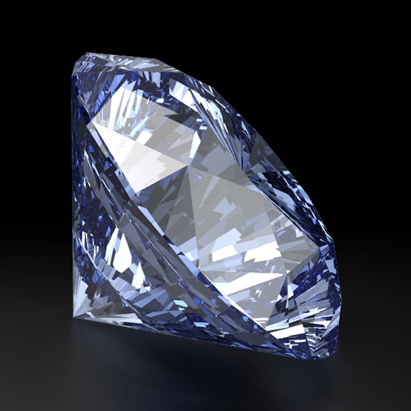
Final Image Preview
Tutorial Details
Program: Adobe Illustrator CS5-CS6
Difficulty: Intermediate
Estimated completion time: 6 hours
Hi everybody! In today's tutorial, I want to tell you about some unusual topic for many illustrators - 3D graphics, as well as need to implement 3D editor in the pipeline vector artist.
Let's see, what a pipeline vector artist is, and what stages it consists of. In most cases, before the vector illustration came to the scene it has passed through the following stages: the Idea (Concept) > Sketch or reference photography > Vector illustration. Sometimes, but not very often, the second stage of the sketch is crossed out because it is useless, since the idea or concept can be fully implemented in vector graphics editor. But let's get back to the typical situation where a shape or color of the object is so complex that for the realization of ideas in the vector it is necessary to reference images.
It is OK if the designer can take a picture of the desired object; the purchase of ready image may require some financial costs and the extending of the license. But what if the desired object doesn't exist in nature at all, or if it exists, it is very rare and expensive, such as a diamond?
Exactly in such situations the aid of 3D graphics vector editor is very handy. In this tutorial we will create a photorealistic blue diamond in Adobe Illustrator based on reference images, prepared in 3D graphics editor. I deliberately do not focus on a specific 3D editor, as they all are nearly equal in their abilities, and your choice is not critical. You can choose the 3ds Max, the Maya, the Cinema 4D, the Blender or any other. I've chosen the last, the Blender, because it is free and doesn't require much installation space. However, I'd like to underline once again - the choice of 3D graphic editor is up to you.
So, let's get it started.
Step 1
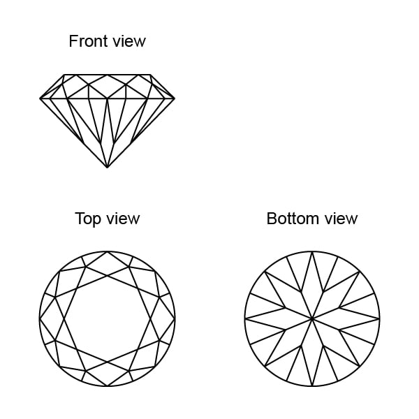
We will model the classic brilliant cut diamond with 57 facets. The schematic representation of our diamond in three planes: front, top and bottom are presented on the figure below. You can save it on your computer and use it for modeling.
The diamond modeling process, material settings and light, as well as visualization, is a topic for a separate tutorial, which won't be considered in our current tutorial. Detailed tutorial on the example of Maya can be found here. We will only look at the basic steps of reference image creation in the 3D modeling software.
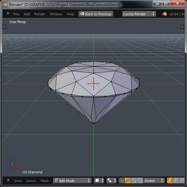
First, create a diamond mesh from polygons.
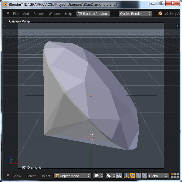
Place it as desired and set the camera.
Add background for the diamond; then set up lighting and materials. However, we will talk about the diamond materials in detail in the next step.
Step 2
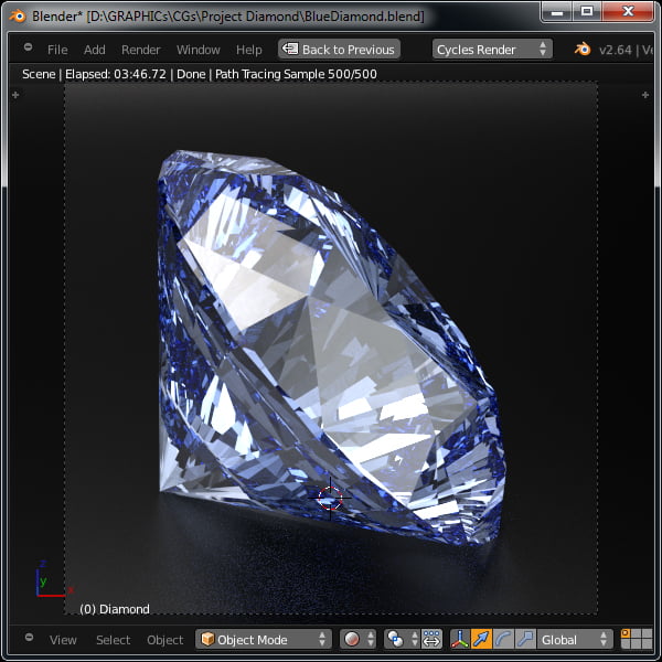
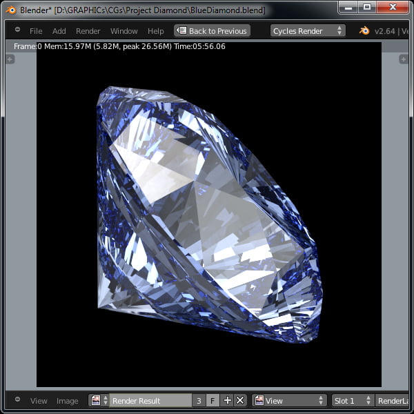
One of the most important parameters of the material for a diamond is the quantity reflections within the crystal. Let's look at the image below. What do we see? There are so many reflections in it; it creates the effect of double vision, although our diamond itself looks pretty sharp. So, in this case, the diamond is almost impossible to vectorize. In real world, the quantity of reflections in transparent environment follows laws of physics. And we can't manipulate them.
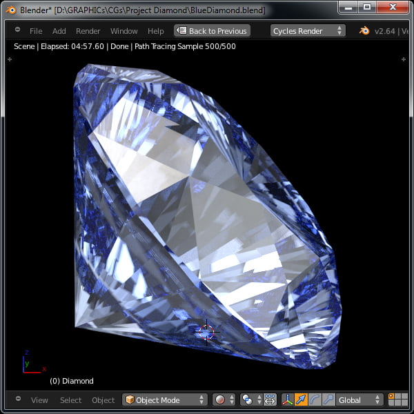
When we work with 3D graphics, we can change all the parameters, including physical. And achieve the desired results in such a way. In the following image altered material properties of the diamond are slightly changed. Look what good effect it had on our result! Double vision has disappeared, our diamond became visually more attractive, moreover, it will be easier to vectorize it now.
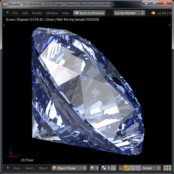
On this stage, our scene is ready to render into the bigger format, which can be used as a reference in Adobe Illustrator. But we won't hurry until then. In the next steps we will try to figure out what other advantages 3D graphic editor can give us to simplify the process of vectorization.
Step 3
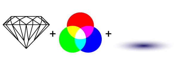
Let's find out what the final bitmap image consists of. First of all, it is diamond shape, then color and shade. The shadow of the transparent objects is called caustic.
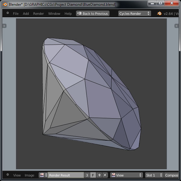
In case with the reference photos, all of its components are inseparable. But in our case we can get them separated. We can render the objects in the Wireframe, in this way the shape of our object will be shown perfectly.
We can get information about the color separately.
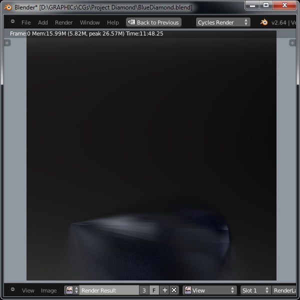
And the shadow of our object or caustic.
It is obvious that the opportunity to work on each stage separately provides some unquestionable advantages in vectorization.
We are almost done with the part of tutorial, dedicated to 3D graphics. Let's proceed directly to the vectorization of our diamond. Archive to this tutorial contains reference images (you can download resource files by clicking the Download button on this page), rendered in large format (2000 x 2000 px), separately for each work stage in Adobe Illustrator.
Step 4
Well, let's get to the main purpose of this tutorial; let's work on creation of photo-realistic vector illustration of blue diamond. Download the Extended Select script and unpack it into Adobe Illustrator (…\Presets\en_US\Scripts\). We will use it sometime later.
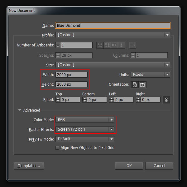
Open Adobe Illustrator, and create a new document with the size of 2000x2000 px. That is the size of our reference images. In spite of the fact that the size is large enough as for vector illustrations, our work with it will be convenient. Also it allows us to create a detailed illustration.
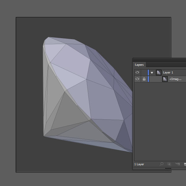
Place the first reference image diamond_wire.jpg in the working area of the document (File > Place…), and lock it in the Layers panel.
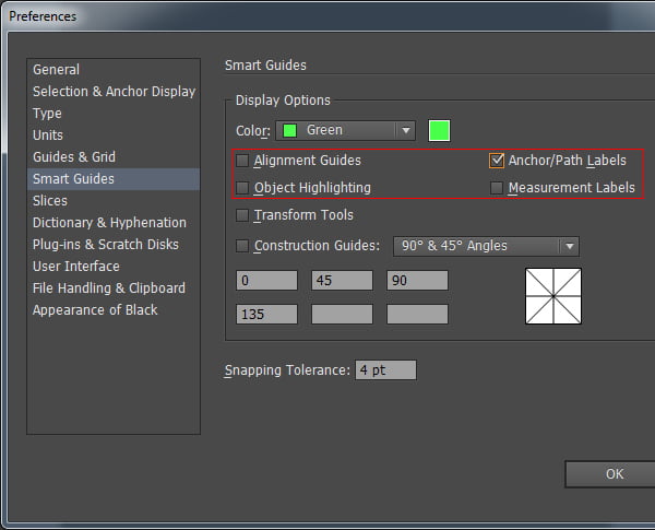
Now open the Preferences (Command / Ctrl + K); then go to settings the Smart Guides and set the parameters as it is indicated on the screenshot below. Then turn on the Smart Guides (Command / Ctrl + U).
Step 5
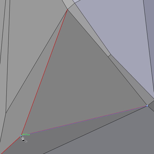
Let's work on drawing. Select the Pen Tool (P), and begin to outline the contours of our image. The stroke width should be 1-2 px, color should be contrasted to the reference color, for example red. The fill must be disabled.
Taking into consideration that contours of the reference image are clearly visible, this step can be completed very fast, and we can move on to the next step.
Step 6
Booking Software for Small Business music / DJSet strikingly Music Appointment Scheduling App Techno.
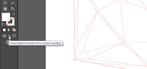
In the last step we have finished creating a diamond shape; we don't need the reference image diamond_wire.jpg anymore, so delete it. Our task now is to create closed paths from the individual segments. To do this, click on the Draw Behind (Shift + D) on the toolbar.
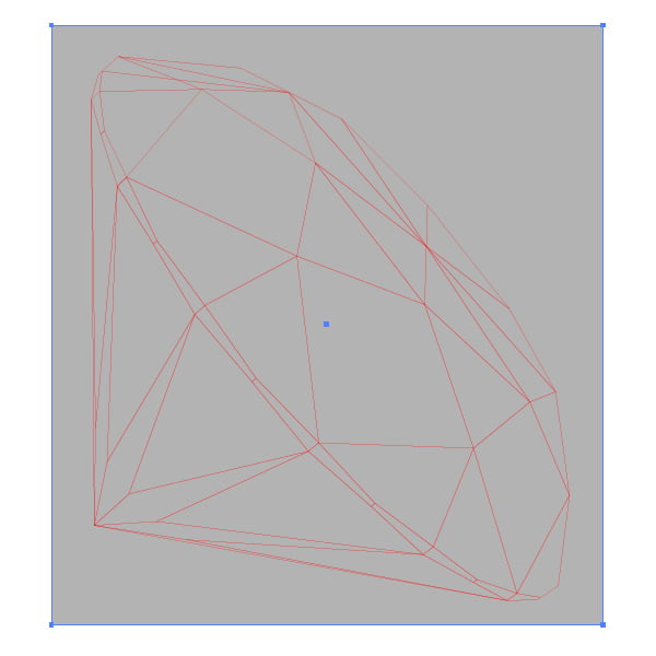
Take the Rectangle Tool (M) and create a rectangle which overlaps the size of the diamond.
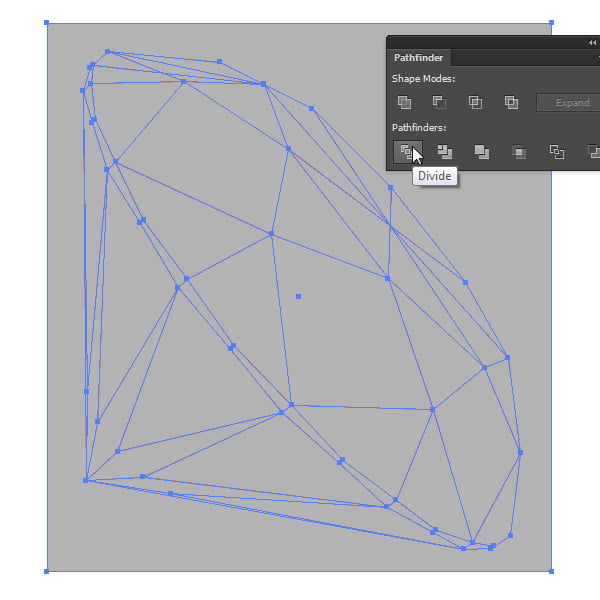
Then select all with the Command / Ctrl+A and click on Divide in the Pathfinder panel.
Step 7
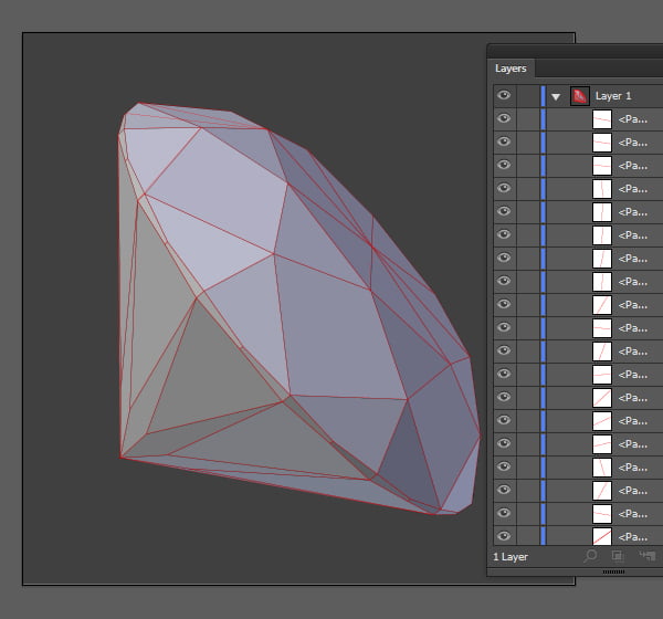
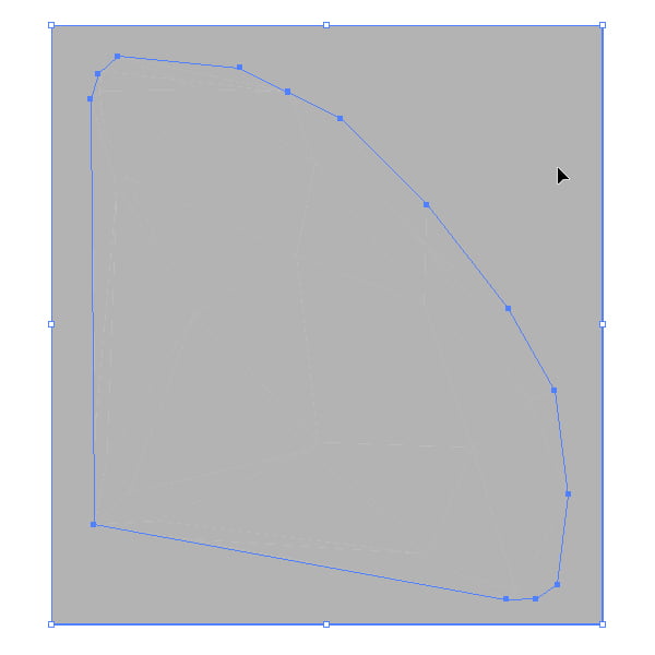
As a result of these actions all the created objects will be grouped. Ungroup this group with the Object > Ungroup (Command / Ctrl + Shift + G). Then select the object that lies beyond the diamond.
And now delete it. As a result, we have now 54 closed paths.
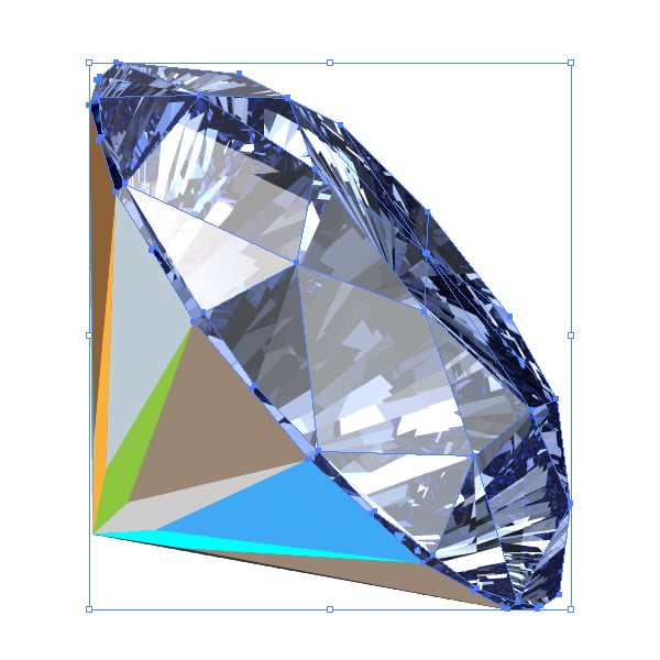
Our objects can be colored differently for our convenience.
Each of these contours is responsible for a certain facet on the diamond.
Step 8
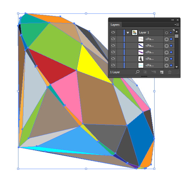
Now we will work on a very long but not very complicated part of our project. Place the second reference image diamond_color.jpg in the working area and lock it (Command / Ctrl +2) in the Layers panel.
Make the group with closed paths from the previous step visible (Command / Ctrl + Option / Alt + 3) and ungroup it (Command / Ctrl + Shift + G).
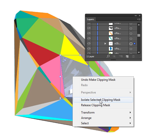
Now duplicate reference image of the diamond (Command / Ctrl + C, Command / Ctrl + F), and while holding down Shift, select any path. In my case, I've selected a light brown path.
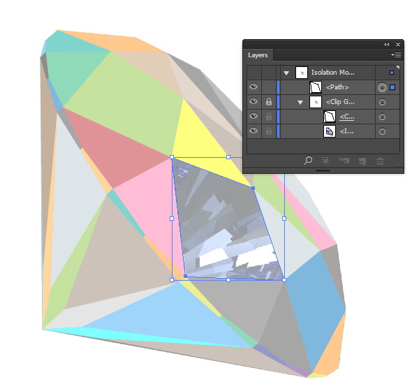
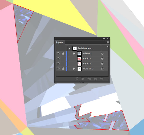
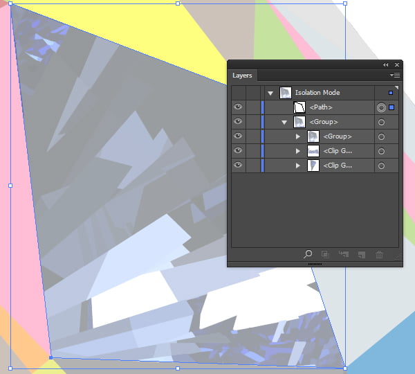
Click on Command / Ctrl +7 (Make Clipping Mask). Now, keep the Clip Group selected; click on the right mouse button and choose the Isolate Selected Clipping Mask from the drop down menu.
So in such a way we went into the Isolation Mode. In this mode only the group containing reference image and Clipping Path is shown in the Layers panel, and all the other objects are hidden.
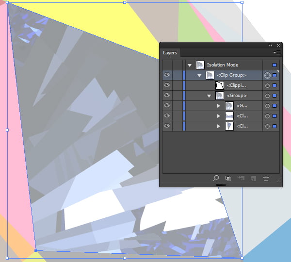
Step 9
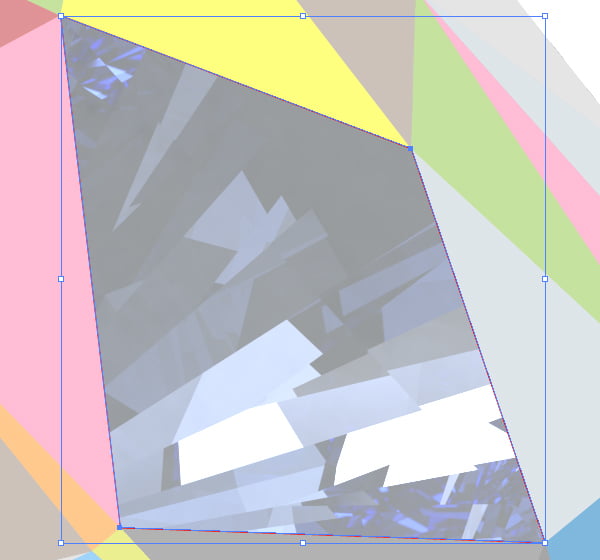
Open the Clip Group; duplicate the Clipping Path (Command / Ctrl + C, Command / Ctrl + F) and move it beyond this group which should be locked after that (Command / Ctrl + 2).
Select a copy of the Clipping Path, which we have just created and change the stroke color to red; width of the stroke should be 1px.
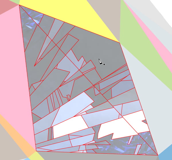
Now take the Pen Tool (P) and outline consistently all the visible contours, which we can discern. It is very important to remember that our accuracy with which we draw the details determines our final result.
Your monitor is very important as well. The better the color reproduction is, more colors you will be able to discern, and the better the result will be.
Step 10
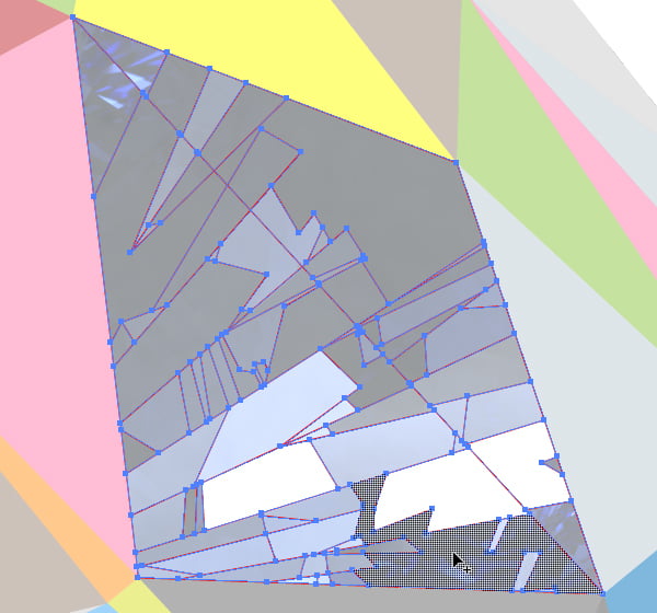
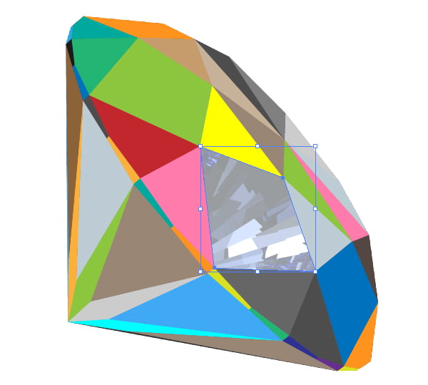
When all the visible contours will be outlined, select everything (Command / Ctrl + A) and take the Shape Builder Tool (Shift + M) and create closed areas.
After that, consistently select each closed path, and take the color from the source image with the Eyedropper Tool (I) for it.
As a result, we should get something like this.
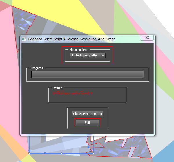
With the two remaining paths with red stroke, we will work in the following step. Now remove the junk which looks like small open paths with some stroke but no fill. Start the Extended Select script from the menu File > Script > Extended Select. In the dialog box, select the Unfilled Open Path; then it will find all the open paths with no fill automatically and will highlight them. Click on the Exit button.
The rest of the selected junk should be simply deleted.
Step 11
The fact is that the reference image within the remaining paths is too complicated for manual tracing, so we will simplify our task, and use the function automatic trace.
Select all paths with fill from the menu Select > Same > Stroke Color; group them (Command / Ctrl + G) and lock (Command / Ctrl + 2) them.
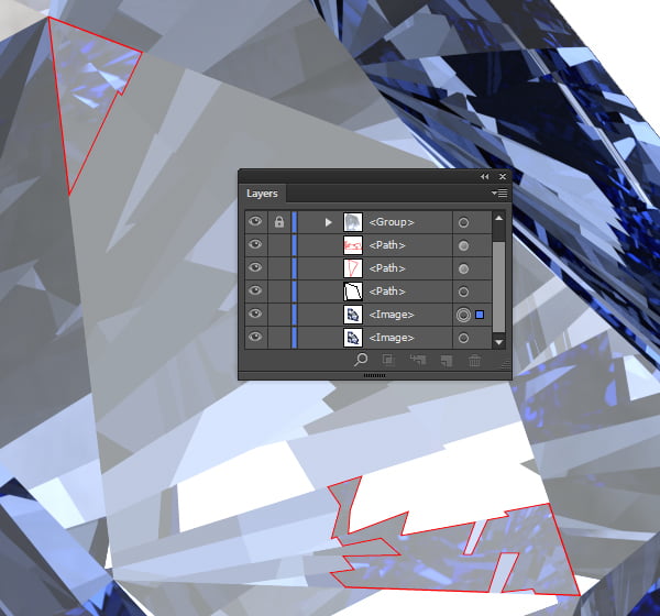
Unlock the Clip Group, and press on the Command / Ctrl + Option / Alt +7 (Release Clipping Path). Now duplicate the reference image (Command / Ctrl + C, Command / Ctrl + F).
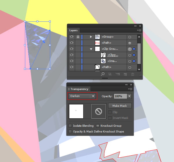
Now we will use the method of framing of raster images into Adobe Illustrator, which was described by Iaroslav Lazunov in this tutorial. Select the raster image and one of the two remaining paths, and click on the Command / Ctrl +7 (Clipping Mask). Change the blending mode for the group from Normal to Darken.
Step 12
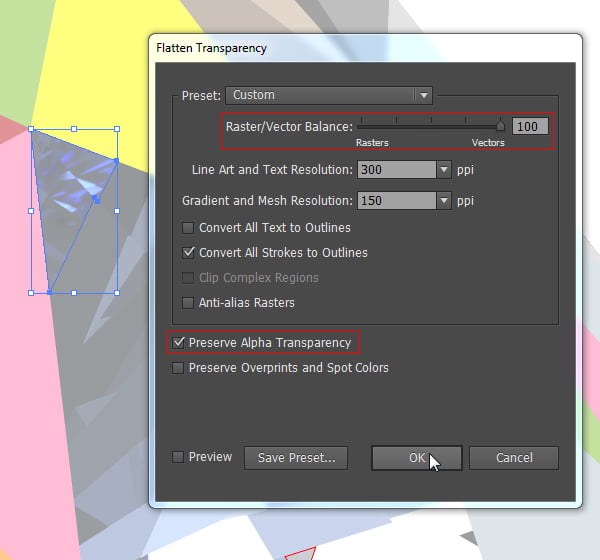
Keep the group selected and go to the menu Object > Flatten Transparency, set the parameters as it is indicated on the screenshot below, and click OK.
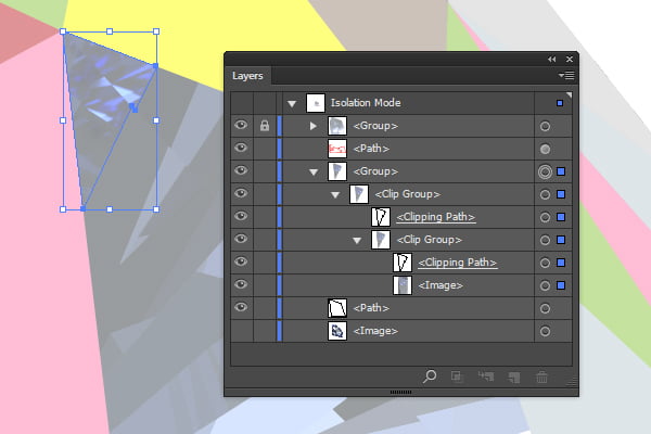
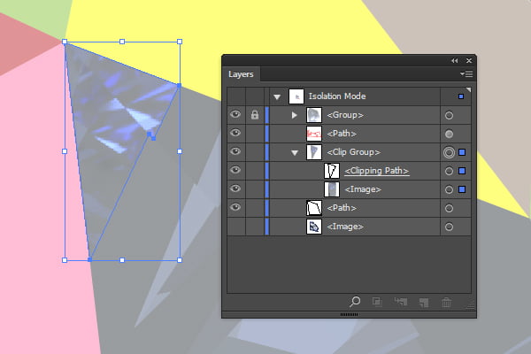
After these actions, the group will contain the cropped raster image and two Clipping Paths.
Remove all the unnecessary objects leaving one Clipping Path and the raster image.
Step 13
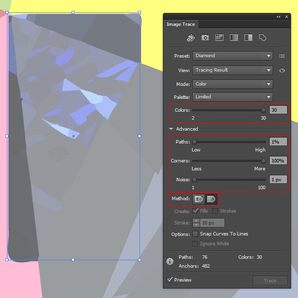
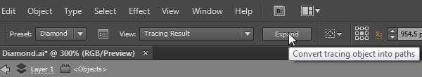
Keep only the raster image selected and go to the menu Window > Image Trace in Adobe Illustrator CS6 or Object > Live Trace > Tracing Options… in other releases of application, and in the dialog box set the parameters as it is indicated on the screenshot below.
Then click on the Expand to convert the trace to a group of paths.
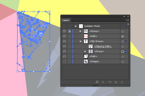
As a result of our actions, instead of a raster image, we have a group of vector objects, which are limited to a clipping mask.
Do the same with the second copy of the raster image and object with a red stroke.
Step 14
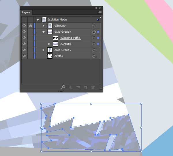
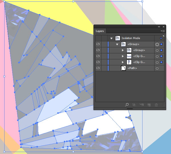
Now group the objects (Command / Ctrl + G), as it is indicated on the screenshot below.
Select the remaining path, and move it up (Command / Ctrl +]).
And press the shortcuts Command / Ctrl + A, then the Command / Ctrl +7 (Make Clipping Mask).
Step 15
For now our work in this area of the image is done. Exit the isolation mode by double clicking on the Back One Level.
That's how our illustration looks like at this stage.
Step 16
Well, we have vectorized one of the 54 areas of the diamond. As you have seen, the tracing process is not a big challenge. The main thing is to do it neatly.
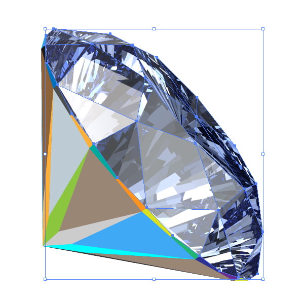
While repeating the 8-19 steps gradually we will vectorize some new facets of our diamond. On the figure below you can see the completed parts of the "crown" of our diamond.
The "girdle" was added to complete our "crown".
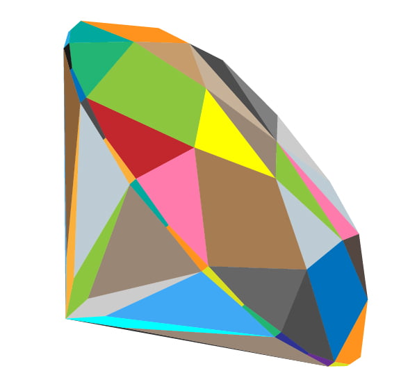
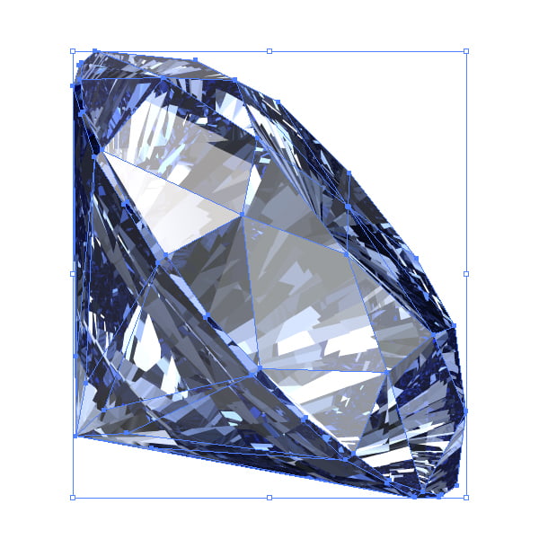
And now, we have finally fully vectorized diamond.
It has certainly taken a lot of time and effort, but the result is worth it!
Step 17
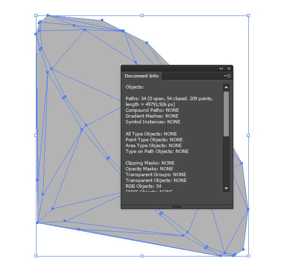
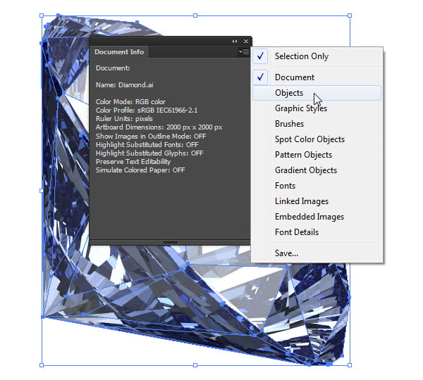
If after the previous steps a copy of the reference image diamond_color.jpg is left in the Layers panel, you can delete it now. We won't need it anymore. Now select everything (Ctrl + A), and open the panel Document Info > Objects.
As you can see there is a certain amount of open paths in the document.
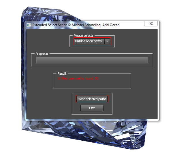
The fact is, that the operation the Flatten Transparency, which we used every time when we crop raster images, leads to the emergence of open Clipping Paths. Why it happens I'm not sure, but I know what to do with it. Open the script Extended Select from the menu Scripts, and select the Unfilled open paths in the dialog box. After a short stint, when it finds all the open paths in the document, and highlights them, click on the Close Selected Paths.
That's it, the work on our diamond finished, but there is still background left, which we'll do in the next steps.
Step 18
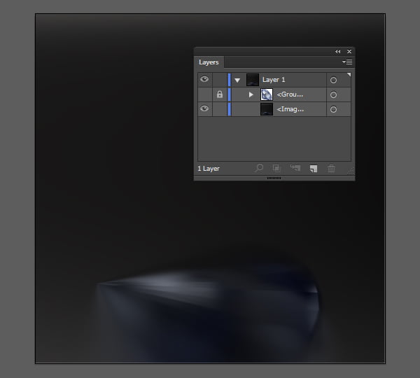
Go to the File > Place and place the last reference file diamond_floor.jpg in the workspace. The group with a diamond hide (Command / Ctrl + 3) in the panel Layers.
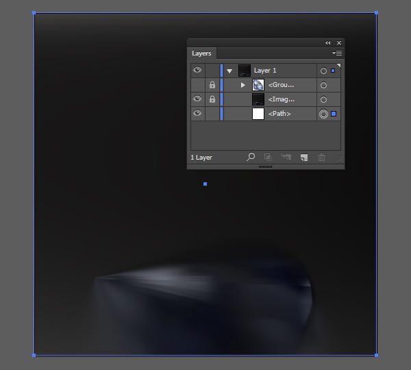
Take the Rectangle Tool (M) and create a rectangle of 2000 x 2000 px.
Move our created rectangle in the Layers panel under the reference image. Lock the reference image (Command / Ctrl + 2).
Step 19
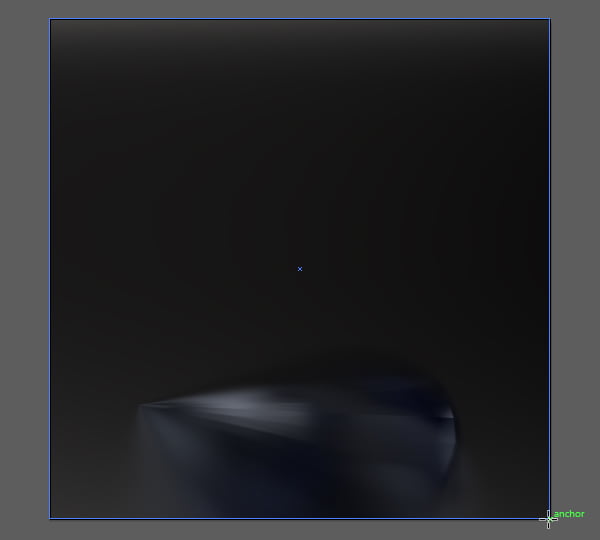
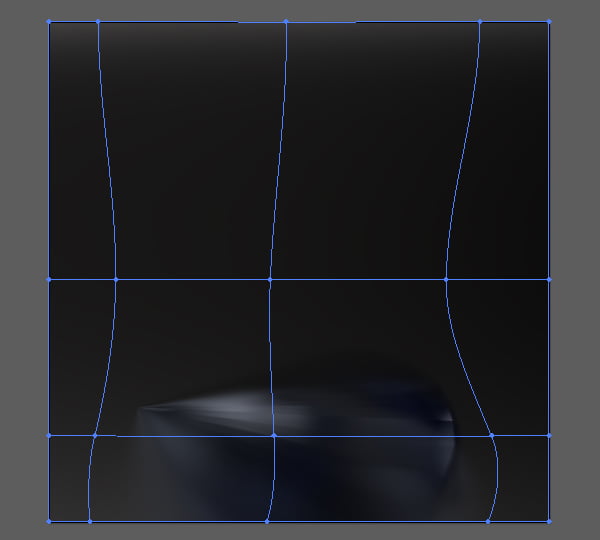
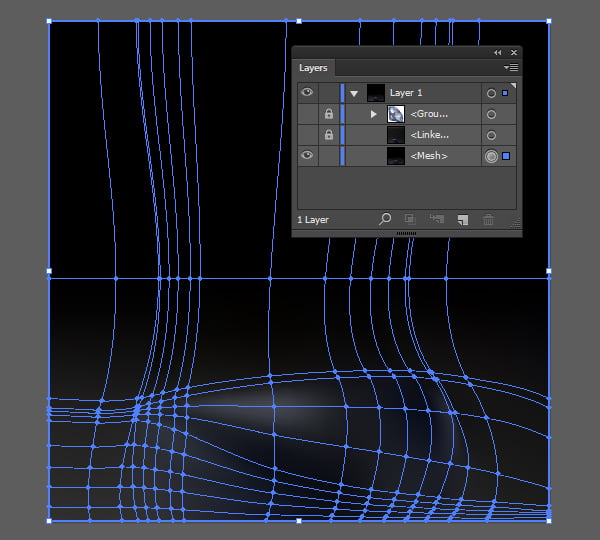
Take the Mesh Tool (U) and put a point approximately in the center of the rectangle. This action converts our rectangle into the Gradient Mesh.
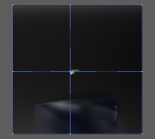
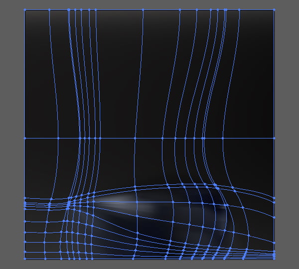
Now, with the Mesh Tool (U) and the Direct Selection Tool (A) we are gradually working on the Gradient Mesh, adding new nodes, and adjusting their position.
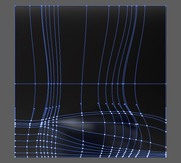
Taking into consideration that some of the reflection will be underneath a diamond, a very big special accuracy isn't needed here. The mesh, which you can see on the figure below, will be more than enough.
Step 20
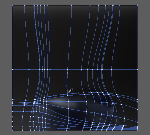
In this step, we will paint the Gradient Mesh. Take the Direct Selection Tool (A) and select the top two rows of the nodes, as it is indicated on the screenshot below, and fill them with black.
Now let's paint the remaining nodes of the gradient mesh into colors, which will be taken from the reference images in location of the nodes. To do this, choose, or make sure that you have selected the Direct Selection Tool (A); then immediately turn on the Eyedropper Tool (I). And next, while holding the Command / Ctrl key select the node; then release the Command / Ctrl and take a color swatch next to the selected node.
In such way, we need to paint each remaining node of gradient mesh.
Here's how the Gradient Mesh will look after our actions.
What is left is to remove the reference image diamond_floor.jpg and turn on the visibility of the diamond group (Command / Ctrl + Option / Alt +3) and unlock it (Command / Ctrl + Option / Alt + 2).
Conclusion
We have finished the creation of a realistic blue diamond in Adobe Illustrator. On the example of this tutorial, I showed you some advantages of use of 3D graphics editors. Our finding is obvious - use of 3D modeling programs opens new features for Illustrator that are not available while using some traditional reference images.
|