|
Today I’m publishing a complete guide to Mesh Tormentor plugin which caused a burst of enthusiastic feedbacks of illustrators from all over the world. This guide is written and illustrated by YemZ, the author of the plugin.
You can download the plugin by clicking the Download button on this page.
Installation of the plugin is conducted by copying a file to the directory YemZMeshTormentor.aip \ Plug-ins \ Extensions \, located as applicable by Adobe Illustrator (eg C: \ Program Files \ Adobe \ Adobe Illustrator CS2 \ Plug-ins \ Extensions \). At the same time Adobe Illustrator itself should not be running. Plug-in can work with most versions of Adobe Illustrator CS2, CS3, CS4, CS5, CS6.
You can read about work with Mesh Tormentor if you use the following links:
Contents
Show axis and / or corner nodes of the mesh
Move the corner node
Convert knots into vertexes
Convert vertexes into knots
Smooth mesh nodes
Mesh colors shift
Reflection of mesh colors
Mesh colors rotation
Color cloning into another mesh
Sew meshes together
Cut the mesh into two
Create a single-cell mesh based on the path
Create mesh grid for Brush
Get the mesh from brush grid
Convert mesh into a set of paths
Guides 1 / 3
Guides 0
The horizontal alignment of nodes and vertices
The vertical alignment of nodes and vertices
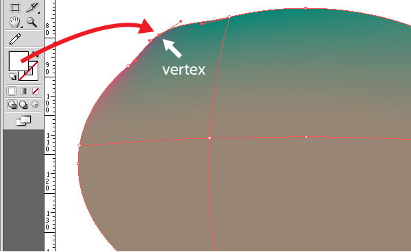
Some terminology to begin with.
- Node — is the point of intersection of the grid lines that defines the color and shape of the cell. Nodes have handles that give the shape of the segment of the cell and the color transition between the neighboring nodes.
- Vertex — is an additional point on the grid lines. It also has handles that define the shape of the segment and the color transition, but do not assign color.
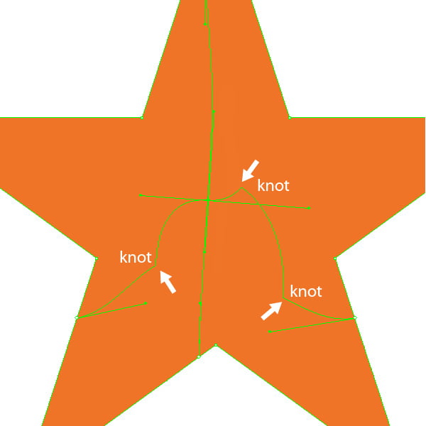
- Knot — is a kind of vertex, but it cannot be controlled directly, therefore it is impossible to achieve the desired result.
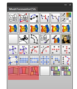
Now let's take a look at the commands from the Tormentor palette.
 | Show axis and / or corner nodes of the mesh |
Selection: mesh or more meshes.
[] created two groups: "Coords" and "Corner Nodes".
Ctrl + [] group will be created: "Coords".
Alt + [] group will be created: "Corner Nodes".
"Coords" displays the axes mesh. Red line - axis I, blue - the axis J.
"Corner Nodes" shows the location of the corner nodes of the mesh.
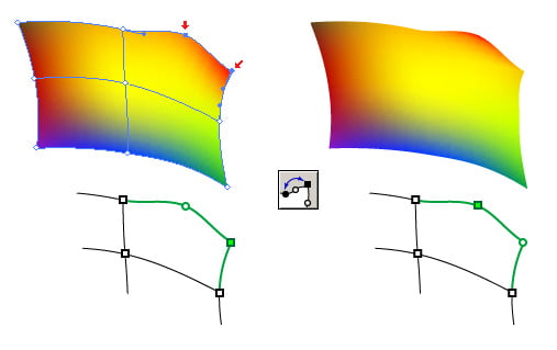
 | "Move the corner node" |
Selection: corner node and valid vertex.
[] Node takes the place of vertex and vertex takes the place of the node.
Valid vertex is a vertex that is located on one of the segments adjacent to the selected cornoer node.
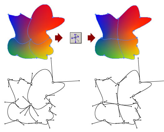
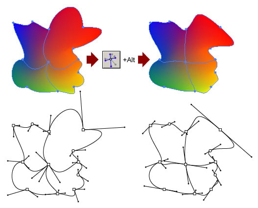
 | "Convert knots into vertexes " |
Selection:: mesh or a few meshes.
[] All knots convert into vertexes.
Ctrl + [] all knots deleted.
Alt + [] deletes all knots with the adjustment of the guides of the nodes and vertexes. Adjustment is done through the guides are adjusted to those which appear in the presence of knot.
 | "Convert vertexes into knots" |
Selection: mesh, a few meshes or some of their nodes (vertexes).
[] Selected vertexes are converted into knots
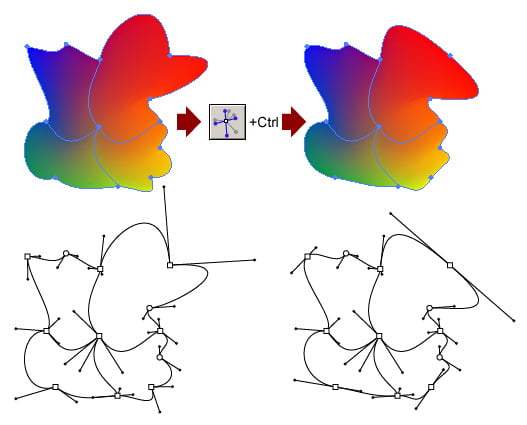
 | "Smooth mesh nodes" |
Selection: mesh, a few meshes or some of their nodes (vertexes).
[] Selected nodes and vertexes are smoothed. Corner nodes are ignored.
Ctrl + [] smooth just the selected corner nodes.
Alt + [] smooth all the selected nodes and vertexes.
 | "Mesh colors shift" |
Selection: mesh or some of its nodes.
[] periodic shift of the colors of the selected rectangular area of the mesh nodes along the I-axis in the forward direction.
Ctrl + [] periodic shift of colors of the selected rectangular area of the mesh nodes along the J-axis in the forward direction.
Alt + [] periodic shift of the colors of the selected rectangular area of the mesh nodes along the I-axis in the opposite direction.
Ctrl + Alt + [] periodic shift of the colors of the selected rectangular area of mesh nodes along the J-axis in the opposite direction.
I.e. Alt is responsible for the shift in the opposite direction, and Ctrl is responsible for changing the axis into J.
Selected rectangular nodes area - it is the smallest regular rectangular (in terms of internal structure, rather than visual shape) fragment of the mesh grid, which contains all the selected nodes.
 | "Reflection of mesh colors" |
Selection: mesh or some of its nodes.
[] colors reflection of the selected rectangular area of the mesh nodes along the axis I.
Ctrl + [] colors reflection of the selected rectangular area of mesh nodes along the axis J.
 | "Mesh colors rotation" |
Selection: mesh or some of its nodes.
[] rotation of the colors of the selected rectangular area of mesh nodes to the right.
Alt + [] rotation of the colors of the selected rectangular area of mesh nodes to the left.
If the selected area has a square shape (in terms of internal structure, rather than visual shape), then the rotation is 45 degrees, otherwise - 90.
Directions to the right and left are relative and their true direction depends on the directions of the mesh axes. Right direction is the direction towards which you have to move around the primary node within a mesh from the axis J to the axis I.
 | "Color cloning into another mesh" |
Selection:two meshes or some of their nodes.
[] colors copying of the selected rectangular area of the upper mesh nodes to the selected rectangular area of the lower mesh nodes.
Alt + [] colors copying of the selected rectangular area of the lower mesh nodes to the selected rectangular area of the upper mesh nodes.
Ctrl + [] colors copying of the selected rectangular area of the upper mesh nodes to the selected rectangular area of the lower mesh nodes with the change of axes I and J.
Ctrl + Alt + [] colors copying of the selected rectangular area of the lower mesh nodes to the selected rectangular area of the upper mesh nodes with the change of axis I and J.
I.e. Alt is responsible for changing the direction of cloning, and Ctrl is responsible for axes shift when cloning.
When cloning, the selected mesh nodes areas overlap taking into consideration the change of axes, and there is selected the area of their intersection which is involved in the cloning of colors.
 | "Automesh — being in development." |
 | "Sew meshes together" |
Selection:Two meshes or some of their nodes.
[] two meshes are sewn into one by bringing together nodes, vertexes and knots at the seamed up sides.
Ctrl + [] two meshes are sewn into one by adding an additional row of cells between the seamed up sides.
Alt + [] two meshes are sewn together by bringing together the nodes, vertexes and knots at the seamed up sides. At the same time the order of the elements pass of one of the sides is reversed.
Ctrl + Alt + [] two meshes are sewn into one by adding an additional row of cells between the seamed up sides. The order of the elements pass of one of the sides is reversed.
I.e. Ctrl is responsible for adding an additional row of cells between the seamed up sides, and Alt is responsible for changing the order of the elements pass of one of the seamed up sides.
For mandatory seamed up sides’ assignment, use partial selection of the corner nodes, which are located at the sides.
Following seam up occurs according to the following procedure:
- Top mesh in the layers palette is sewn to the second in a row.
- The resulting mesh is sewn to the third one.
- The resulting mesh is sewn to the fourth.
Selection: A few (more than two) meshes that contact each other with the corner mesh nodes forming the well-formed grid.
 | "Cut the mesh into two" |
Selection:lateral mesh node.
[] Mesh is cut into two along the line passing through selected lateral node.
Selection:Two side vertexes located on opposite segments of a single cell.
[] Cell is divided into two along a straight line drawn between the selected nodes. In this case mesh remains intact.
 | "Create a single-cell mesh based on the path" |
Selection: Path or some of its (their) anchor points. There should be at least 4 selected anchor points of each path.
[] The path is converted into a mesh. Mesh nodes are four of the most sharp anchor points among the selected ones. Mesh nodes are filled with gray.
Ctrl + [] path is converted to a mesh. In this case, the path itself is not deleted. Mesh nodes are four most acute among the selected control points. Mesh nodes are filled in gray.
Alt + [] path is converted into a mesh. Mesh nodes are four of the most sharp among the selected anchor points. Mesh nodes are filled with fill color of the path (if there is no fill, than with the color of the stroke, and if there is none — than fill with gray).
Ctrl + Alt + [] path is converted into a mesh. In this case, the path itself is not deleted. Mesh nodes become four most sharp anchor points among the selected ones. Mesh nodes are filled with the fill color of the path (if there is no fill, than with the color of the stroke, and if there is none — fill with gray).
I.e. Ctrl is responsible for saving the original path, and Alt is responsible for filling the mesh with color, taken from the path.
 | "Create mesh grid for Brush" |
Selection:mesh or meshes.
[] The mesh is transformed into a special grid, resembling the original mesh, and comprising the pathes that allows you to use it as an element of the brush.
 | "Get the mesh from brush grid" |
Selection:Special brush grid or a few grids.
[] Brush grid is transformed back into the mesh.
 | "Convert mesh into a set of paths " |
Selection:mesh or a few meshes.
[] group of paths "MeshGridTL" is created, passing along the segments of the original mesh.
Alt + [] a group of paths "MeshGrid" is created, each of which corresponds to a particular segment of the mesh.
Ctrl + [] a group of paths (including singlepoints) "MeshPoints" is created, showing nodes, vertexes, knots, true and reflected guides.
 | "Guides 1 / 3 " |
Selection:mesh, a few meshes or some of their nodes (vertexes).
[] In selected nodes (vertexes), all the guides change in size, the length of each becomes equal to 1 / 3 of the distance between node (vertexes) and the neighboring (to the side of the guide) node (vertexes).
Alt + [] the manner indicated above change only the guides, which are allocated between the neighboring nodes (vertexes).
 | "Guides 0" |
Selection:mesh, a few meshes or some of their nodes (vertices).
[] In all the selected nodes (vertices), all the guides change in size, the length of each becomes equal to zero.
Alt + [] the procedure described above allow to change only the guides, which are allocated between the neighboring nodes (vertexes).
 | "The horizontal alignment of nodes and vertices" |
Selection:mesh, a few meshes or some of their nodes (vertexes).
[] The selected nodes and vertexes are horizontally aligned.
Alt + [] Selected nodes and vertexes are horizontally right-aligned.
Ctrl + [] Selected nodes and vertexes are horizontally left-aligned.
 | "The vertical alignment of nodes and vertices" |
Selection: mesh, a few meshes or some of their nodes (vertexes).
[] The selected nodes and vertexes are vertically center-aligned.
Alt + [] Selected nodes and vertices are vertically upper edge-aligned.
Ctrl + [] Selected nodes and vertices are vertically bottom edge-aligned.
Plugin installation is done by copying a YemZMeshTormentor.aip file to the directory \ Plug-ins \ Extensions \, located as installed by Adobe Illustrator (e.g. C: \ Program Files \ Adobe \ Adobe Illustrator CS2 \ Plug-ins \ Extensions \). In this case, Adobe Illustrator itself should not be running. Plugin can work with most versions of Adobe Illustrator CS2, CS3, CS4, CS5, CS6.
You can download the plugin by clicking the Download button on this page
You can meet with the plug-in developer in the article Interview with Iaroslav Tabachkovsky aka Yemz
Follow us if you want to be the first to know about the latest Adobe Illustrator tutorials and articles. Vectorboom team works for you!
| 


 ! Can anyone give me a hand with this ? I really need this function so helpful for my work you know …